My Projects

On this page, you'll find a selection of my previous projects. My software projects consist purely of code and programming. My CAD projects showcase my 3D models and designs, and my mechatronics projects combine software, electronics, and CAD.

Software Projects

Astronomy Game

May, 2017

Astronomy game

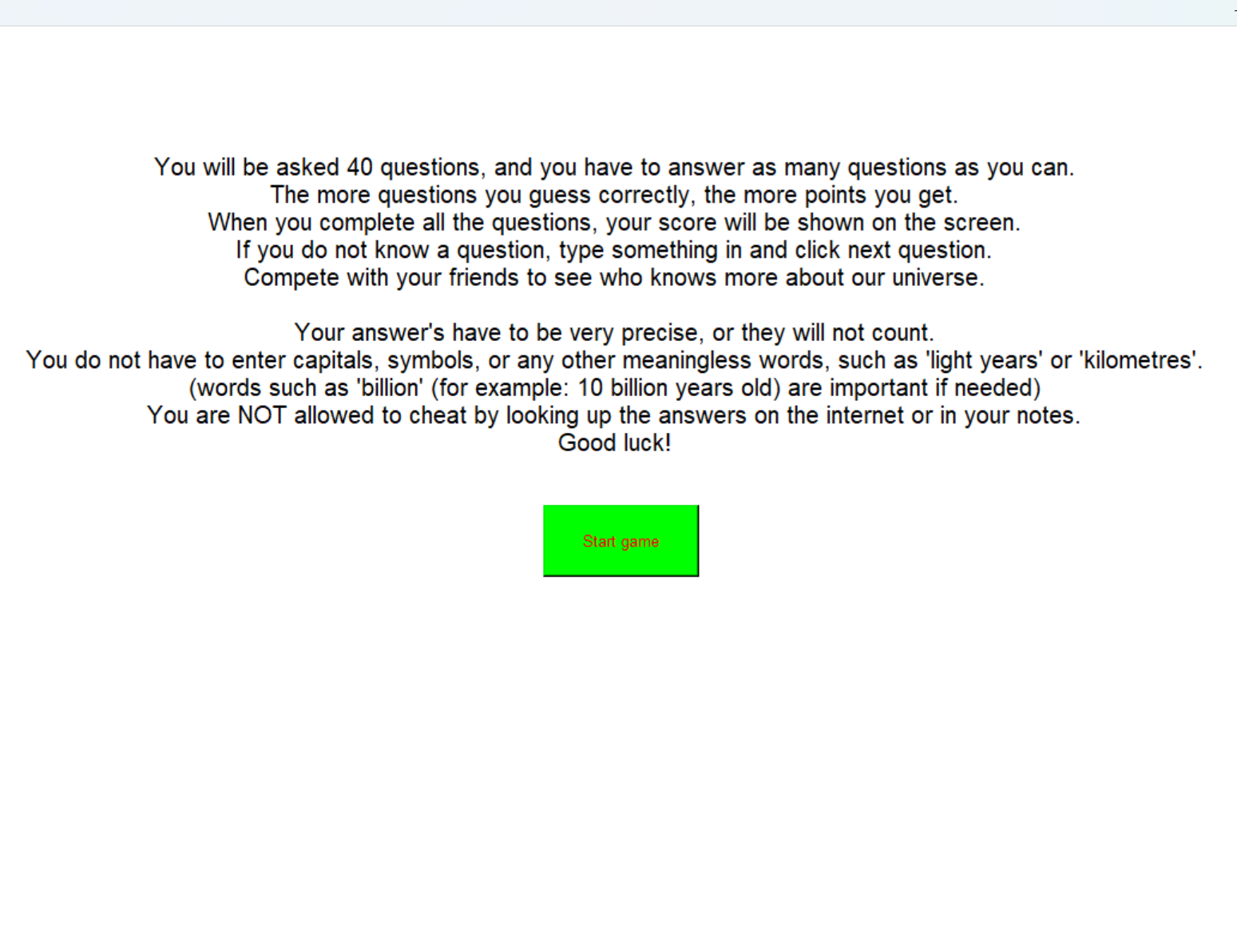
I began learning coding with Python, which I used to make a bunch of little games. One of the games is an astrology quiz game, which I used as a science project.

This is a JavaScript remake of the original Python code, so you can actually try it out! Just click the rules button and see how well you can do.

The original Python code opened a new window to play in, which was something I had just started learning at the time. It was a fun idea I came up with to use as a science project, and it turned into a fun class trivia contest.

If you're curious, you can view the original code and download the files to try it out yourself.


Flappy Bird

May, 2023

Flappy bird game

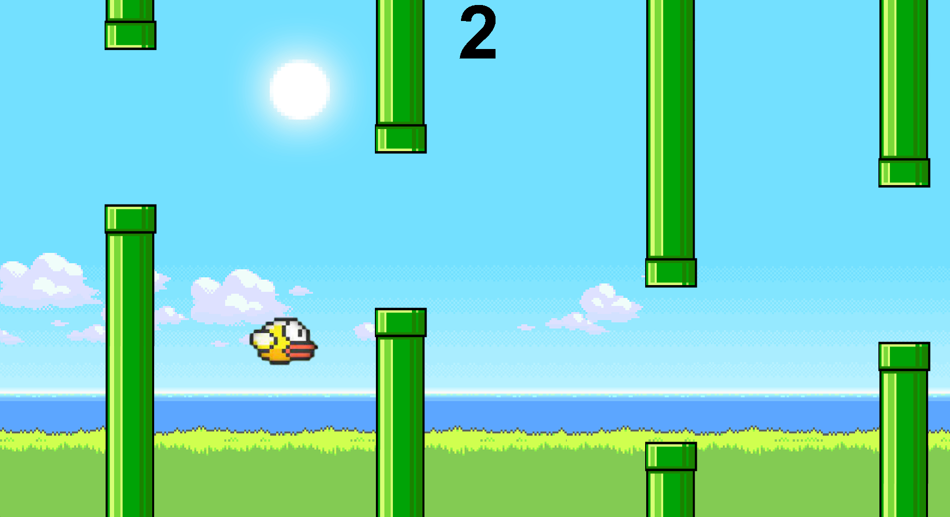
After learning the basics of the java programming language in grade 11, the final project in the course was to create a game using everything that we learned. I chose to make a recreation of flappy bird with a 2-player feature.

My first high school computer science class was all about learning the basics of coding, logic, and graphics through Java. At the end of the course, each student created their own game using what we had learned in class.

When the game is launched, the user is met with a title screen that gives 3 options — play the game with one or two players or read the rules. The single-player option works exactly like the original popular Flappy bird game, where the player uses a key to fly a bird through pipes as long as possible, including the score and even sound effects.
The multi-player is a twist on the game, where two people could play simultaneously and the player who lasts the longest is the winner.

If you want to try the game out yourself, you can find the game files here and run it in a Java IDE.
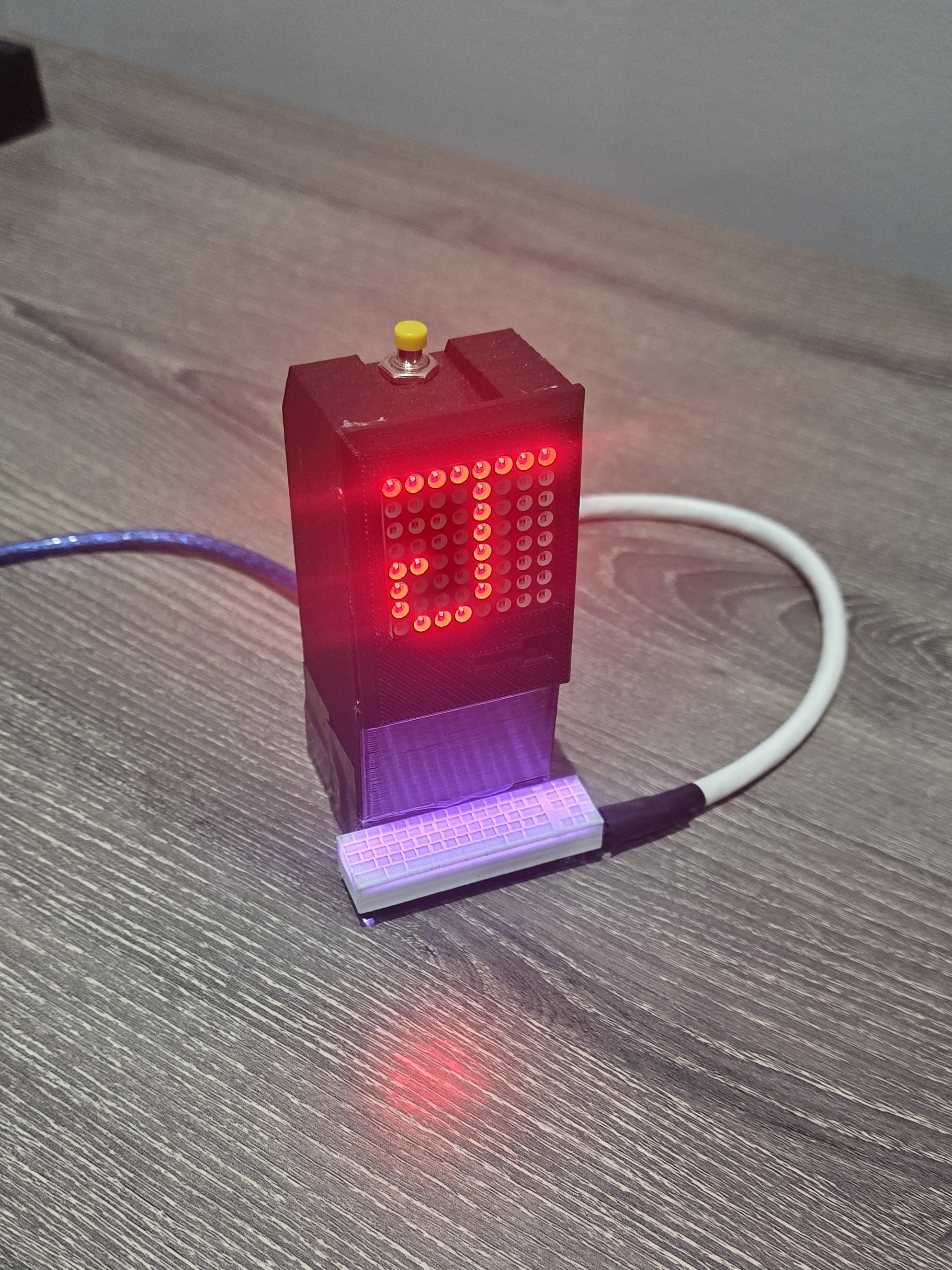

Mini-bot

March, 2025

Mini-bot autonomous loader

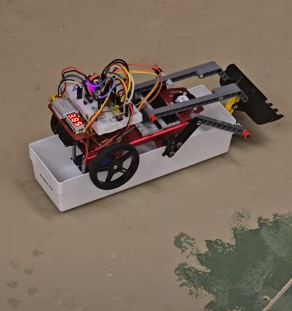
Throughout my Mechatronics and Robotics Design 1 course, we were tasked with programming a mini-bot to perform certain tasks. For example, it needed to be able to follow a line or pick up / drop items from one location to another.

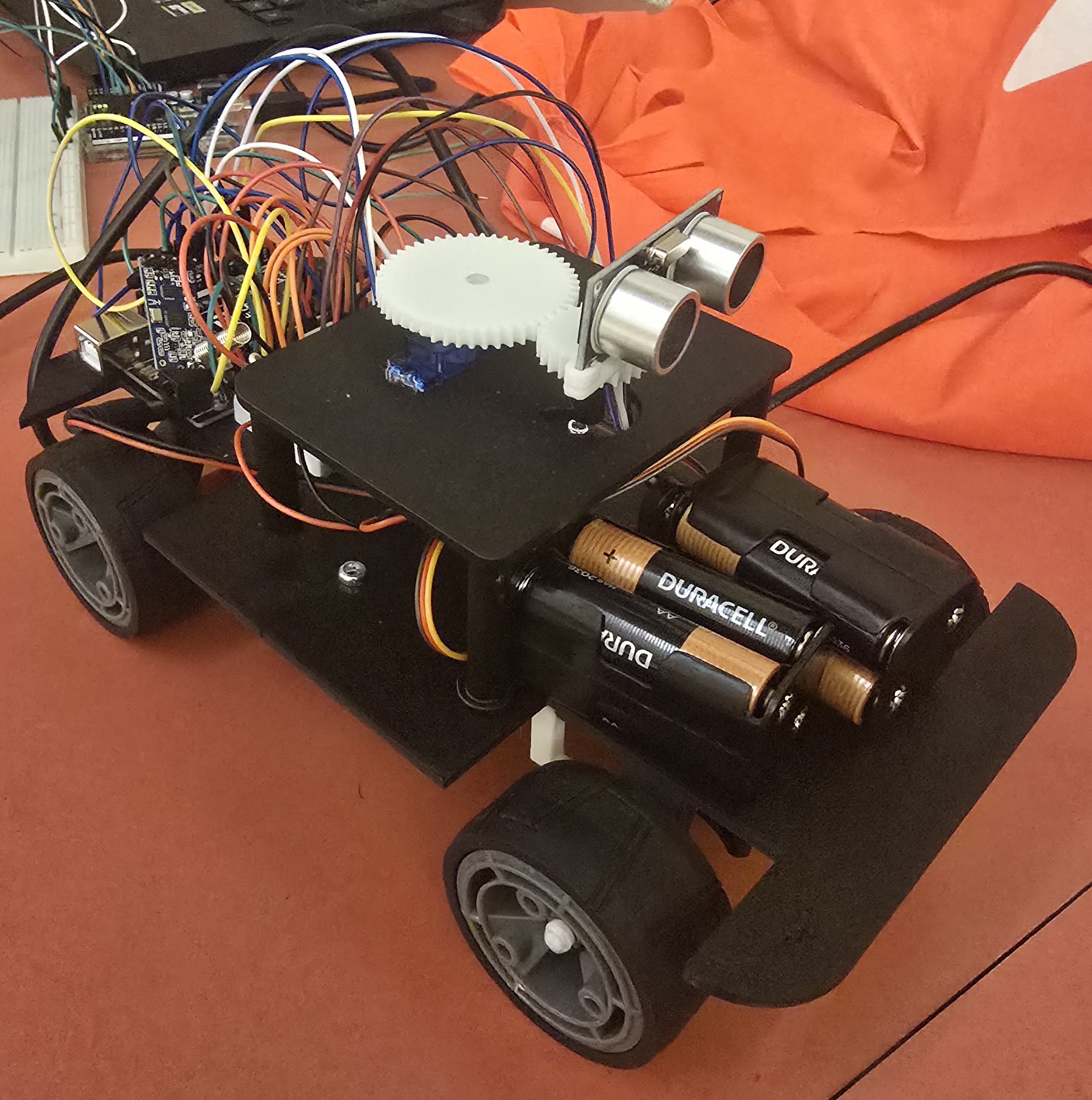
This project spanned 6 weeks, during which each group learned and practiced coding bots using Arduino software and hardware components. We learned how to use different sensors, such as distance sensors and colour sensors, as well as how to control servo motors for the wheels and bucket system.
The final project was putting everything we learned together — this included line following, turning on intersections, and picking up/dropping items using the bucket and arm system.

Although the tasks seemed simple at first, there were many challenges that required unique solutions to make the code function correctly. The main problems were traction, battery life, and using open-loop code. The first and simplest fix: the traction, which became an issue when the wheels became dirty and started slipping on the ground. As the wheels became more slippery, the code needed to be slightly adjusted very often to counteract this, so we cleaned the wheels with a toothbrush.
The LiPo batteries were hard to work with, since even if a good battery was used, it would be depleted very quickly. The more they were used, the less power they gave to the motors and sensors, which slowed down the bot and changed the timings. Since we were using specific timings for turns, the battery always needed to be fully charged to be consistent.
This leads into the next problem, which is using an open-loop system — This is where everything the bot does is based on delays without any feedback from any sensors. Clearly, the solution would be to code in a closed-loop system, where the bots actions are determined based on sensor readings and feedback. The challenge with this is that we did not have many sensor options, so we would need to create complex algorithms for some simple actions. We found a good balance for using open and closed-loop code, and only used open-loop for turns at intersections.

As part of the final submission, each group was required to record a short video of the entire run. If you want to watch my group's submission, click this link, turn up the volume and enjoy! (feat. AI Sir David Attenborough)


CAD Projects

Rollercoaster

April, 2024

3D-printed marble rollercoaster

The final project in my grade 12 physics class required the students to create a marble rollercoaster with loops, turns, corkscrews, and more. I chose to design and 3D print the track and put it all together inside a wooden frame.

By the time I began designing the track, I had been learning and practicing with CAD, using software like OnShape to create simple models. When the rollercoaster project was assigned, I decided to 3D-print the track — unlike other groups who built theirs manually — to both practice and develop more CAD skills.
While creating different designs, I encountered problems like the track being too weak or the rail spacing being too wide or too narrow. After many iterations, the different track parts were measured to have the right balance of strength and stability for the ball. I created many different types of track segments, such as a straight track, a spiral track, and a hill track:
CAD model of straight track CAD model of spiral track CAD model of hill track
Each section, including many other parts, was 3D-printed and connected using custom clips to create the full marble run.


License Plate Holder

April, 2025

3D-printed license plate holder

For many cars, attaching a front license plate requires either drilling into the front or using a very expensive bracket. I designed and 3D-printed clips that attach to the front of the car and securely hold the license plate.

I created this design when a front license plate was needed for a new car. There weren't many good options — either drill into the bumper, use the tow hook hole, or buy an expensive mount that even reduces a car's performance. I needed a system that was non-invasive, secure, and easily attachable to the car.
Using SOLIDWORKS, I created several possible ideas for what the design could look like. After printing many prototypes, the final design consists of two pairs of clips that are attached at two points on the bumper. One clip hooks onto and under the bumper, and the other part clips onto the top. The license plate is then screwed on, attached to the two parts, and simultaneously secures the clip to the bumper even more.
CAD model of hook piece CAD model of top piece
The clips are printed with a PAHT-CF material, making them weather-resistant and very durable.


Mechatronics Projects

Mini-Mac

May, 2023

3D-printed mini Mac

The final project for my grade 12 Computer Engineering class — a small 3D-printed mini Mac computer with an LED matrix screen that displays different images for each click. It also includeds a keyboard with lights (and even plays music).

After learning more advanced Arduino electronics and code, each student was tasked with building a model of a Mac computer. We were given a 3D-printed casing, in which all the electronics were placed, along with all the materials we needed to use. The Mac consists of an 8x8 LED matrix, a button, an LED strip, and other parts. When the button is pressed, the screen changes and cycles through different designs. On the last part, the speaker inside plays a tune before looping back to the start. The Mac also has a keyboard attached to it with an LED strip inside, giving it working lights that can change colour. While the melody plays, the keyboard begins displaying rainbow lights.

The code is written in the Arduino compiler, and uses libraries such as the Adafruit NeoPixel and LedControl libraries. For the music, each note in the melody is assigned a specific value and stored in an array, which is then played with specific durations and timed delays, producing different beat lengths and forming the full melody.


Water Filter

November, 2024

Arduino-controlled water filter

My first university engineering project was putting together a working water filter. My team and I designed 3D-printed parts and created code to make the filter function properly.

This project was designed as an introduction to the engineering process. Each team held weekly meetings to determine and analyze data, create designs, and document progress through reports. It taught teamwork/collaboration and problem solving — skills that are needed for creating a functional prototype within a specific time frame.

The purpose of the project was to create a working prototype of a water filter. Using centrifugal and peristaltic pumps to move the water, turbidity sensors to measure the water clarity, and a variety of other sensors and devices, the filter uses aluminum sulfate (alum) powder to clump soil and dirt found in the water together, which is then transferred through a syringe packed with layers of filtering materials that blocks any remaining particles, leaving only clear, filtered water.

To begin the project, we were given a hypothetical scenario in which a community needed a drinking water system. We were given multiple options, each having its own advantages and drawbacks, and we needed to choose the most appropriate one based on specific criteria. After figuring out all the logistics and constraints, we began designing the main water filter system. While all the necessary materials were provided, many parts still had to be designed and implemented by our team. For example, we had to calculate motor torque, design a powder dispensing system, assemble all the parts into a functional prototype, and write code for the entire system to filter the water properly.
The team used SOLIDWORKS to create CAD models and Arduino software to write code for the electronics. After many tests and improvements, the final prototype filter worked correctly.


3D-Printed Car

March, 2025

The Li-Car — a 3D-printed car with a 360 degree radar

As the final project for my data structures and algorithms course in first year, my group designed and coded a working 3D-printed car with a 360 degree radar, featuring a working differential drive, steering system, and 360 degree radar.

The idea for a functional 3D-printed car model first came from inspiration from the way real cars work. At first, I found a 3D model of a differential gear system (click here to view the 3D model on Thingiverse), and designed a frame with the differential system implemented in it. After making some adjustments, I added a motor with a gear reduction to power the differential system with more torque, and wheels to the custom axles.

Now, even though the car was able to drive, it needed a steering system. To continue making the car as realistic as possible, I designed a steering system that works very similarly to one found in real cars. A 180-degree servo motor was used to power the steering — the servo is connected to a rack and pinion, which transfers rotational to linear motion. The rack is then connected to rods called arms, with ball joints (tie rods) for full range of motion. The arms are then connected to the front wheels, allowing them to rotate and turn. To view the inspiration for this design, click here to view the YouTube video describing how car steering works.
Finally, after all the designs were finalized, they were assembled on a frame, creating a working drive system for the car.

Underside of 3D-printed car model

After designing the main car, we needed to somehow implement a radar with a 360-degree turning radius. We only had 180-degree servo motors, so I designed a 2:1 gear ratio that allowed the ultrasonic sensor to rotate in every direction.
For the electronics, I used an H-bridge motor driver to allow reverse driving, and a transistor for speed control. Along with steering, a servo motor was used to rotate the ultrasonic sensor, all of which were controlled by an Arduino UNO microcontroller.

After the project was finished, I wanted to improve the design — I added a motor driver to supply more current to the motor, powered by a larger battery setup. I also tried adding more motors to the drive system, but too much friction was a major issue. Even with many other possible improvements, this project gave me the opportunity to practice and develop my CAD and electronics skills.

Hackathon Bot

February, 2025

Hackathon mini bot

During the 2025 UTRA Hackathon at UofT, we were tasked with putting together and coding a bot that could drive through a maze, pick up objects, and be able to detect colours underneath it in order to perform certain tasks.

My very first hackathon — where each team gets two days to scramble and build a bot as quickly as possible that manages to perform certain tasks. The objectives for that event were to navigate through a maze, drive to the center of a target using colour detection, and navigate/place a flag in a specific location.

To start off, my group was given a set of 3D-printed parts and electronics to use throughout the event. We began assembling the main body, which we needed to figure out as quickly as possible to leave time for programming. At first, with a few setbacks, we managed to get the driving working, which used two motors controlling each front wheel. While starting some code for the colour sensor, we began working on putting together the arm, which would grab items and hold the ultrasonic sensor.

With a tight time frame to build and code the bot, we were rushed to finish on time, which led to many difficulties. At first, we needed to figure out how to put together all the hardware, which ultimately required a lot of glue and attempts. However, after finishing the main frame and drive system for the bot, wiring all the electronics to the Arduino was much easier and quicker. Once most of the electronics were connected, we needed to write code to make the bot perform all the tasks correctly, which was the most tedious task. Initially, we needed to learn about code implementation for each sensor, since most of them were new to us. Then, plenty of testing was required since code is not the easiest to get working. In the end, we were not able to get the bot working for every challenge, and it didn't even work well for the one we focused on, but participating in the hackathon prepared us for future hackathons and figuring out how to use different electronics in general.
We named our bot "Robotic Anxiety" because of its visual resemblance to the character "Anxiety" from Inside Out, and because of all the anxiety our team went through during the event. You can click here to visit the Devpost page about our bot.